2.2. Extracting FW4 CAD surface
The SALOME Geometry module is designed for:
- Import and export of geometrical models in IGES, BREP, STEP, STL, XAO and VTK formats;
- construction of geometrical objects using a wide range of functions;
- viewing geometrical objects in the OpenCASCADE (OCC) viewer;
- transformation of geometrical objects using various algorithms;
- optimization of geometrical objects;
- viewing information about geometrical objects using measurement tools;
- designing shapes from sketches;
- defining fields.
The Geometry module includes many GUI features and functions that enable basic CAD modelling and allows importing several standard CAD interchange formats listed in a table below.
| Format | Short description |
|---|---|
| BREP | Used to store 3D models and is part of Open CASCADE Technology (OCCT) |
| STEP | Standard for the Exchange of Product model data |
| IGES | Initial Graphics Exchange Specification - vendor neutral file format of CAD model |
| STL | File format native to the stereolithography |
| XAO | CAD file format |
In this tutorial we will create surface CAD models of ITER blanket obtained from ITER design office. From these defeatured models we can then create meshes required for SMITER field line tracing.
Before launching SMITER we need to ensure that STEP files are available for import and some intermediate study files for later tutorials by
make -C study/step
make -C study/tutorial
or look under the location pointed by environment variable
$SMITER_STUDY_EXAMPLES_DIR for ITER-Blanket.stp that
we will be importing shortly.
Note
In continuation we will be referring to the files provided under
the study/ directory that may also be provided as a
system-wide read-only source of examples provided with SMITER under
$SMITER_STUDY_EXAMPLES_DIR for tutorial and/or resources
for testing and starting points that should appear in dialog box as
a shortcut.
2.2.1. Importing geometry
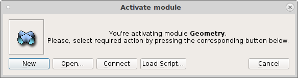
We start SMITER and start a new case by clicking ont the Geometry module
icon  where we select New.
With Geometry module activated we import a STEP file
ITER-blanket.stp through menu that is located under study/step
directory as described above. This STEP file of around 200MB was
exported by CAD “modeller”. STEP is a standard CAD data interchange
format. After the file was read the following question appears
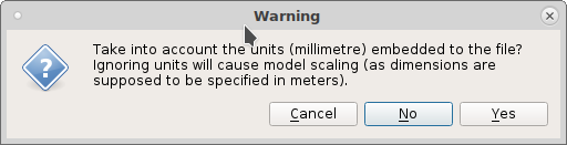
to which we respond by No and then it will take several minutes to interpret all geometrical entities described inside. The “import” process is quite commonly long as the CAD kernel is interpreting the commands and builds the model in the same manner as it was designed by performing necessary geometric operations and checking for occlusions and trimming of algebraic surfaces by boundaries prescribed.
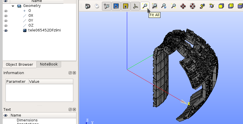
By clicking on the “eye” ![]() in front of assembly name
in front of assembly name
tele0654... we show or hide selected object. When
![]() is enabled then by clicking on Fit All
icon the assembly appears completely. Since this is a group of many
parts it appears in a grey color.
is enabled then by clicking on Fit All
icon the assembly appears completely. Since this is a group of many
parts it appears in a grey color.
By selecting the assembly object it will appear highlighted and then from the menu we select Solid Sub-shapes Type.
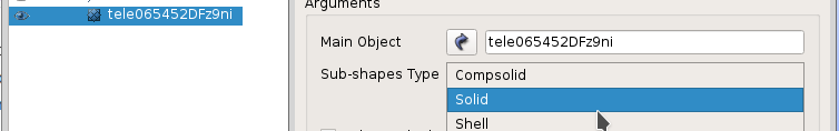
By clicking Apply and Close and confirmation with Explode the shape containing 552 sub-shapes will be created. The exploding operation may take few minutes to complete as it is creating a new modelling tree that can be seen in the study.
We will assign Auto Color property by right clicking on newly exploded assembly that has now “eye” hidden and will appear in different colors shortly.
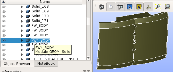
By clicking on the first wall panel number 4 the it is shown as
selected in white and can be found highlighted under name FW_BODY
somewhere in the middle of the Object Browser. We can then
rename it to FW4_BODY by double click on the name or F2 for
easier identification later on.
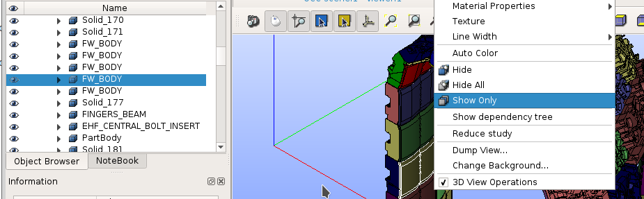
By right-click on the panel 4 again we select Show Only to continue working on this object in sequel.
We are only interested to extract plasma facing surfaces for meshing. This includes edges that may be hit by particles. At this point it may be good to save the study somewhere with . It can be observed that the file saving and opening is much faster than importing. Because the modelling tree does not need to be checked or interpreted also reading models from HDF study files is quick comparing to STEP import. The size of binary HDF study is half of the STEP file in ASCII format.
It is also a good practice to leave everything in study in order to
see complete data at some later time and be able to modify the case
for additional studies. Although only FW4_BODY is shown when
saving, everything is saved, except the view on the data that follows
usual hierarchical principles of display.
2.2.2. Selecting plasma facing surfaces
At this point we may continue or open the
study/tutorial/geom1.hfd file and again select FW4_BODY to
be on the Show Only.
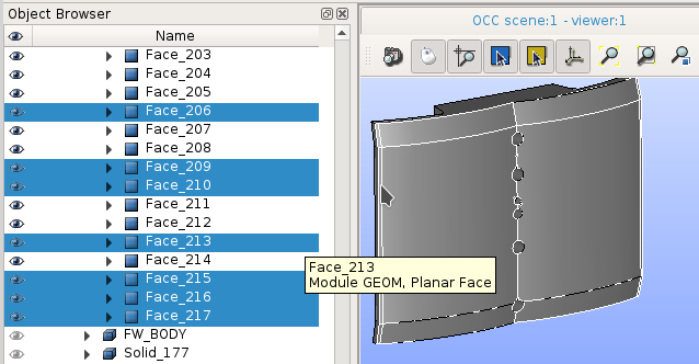
By having FW4_BODY selected we again create . We change Sub-shapes Type to
Faces. By presing Apply and Close and
confirming explosion then 217 faces are created.
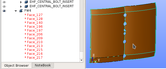
With Shift and mouse click we select faces including edges as shown on the following image.
From these face selection we now create and change shell Name to FW4.
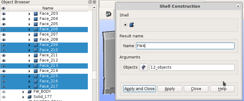
After Apply and Close new shell appears at the bottom of
the Object Browser. We may wish to change the color of the
panel and save the study at this point before proceeding to create a
mesh from the newly created FW4 shell or continuing with the shell
extraction on the remaining panels.
The study with extracted FW4 is available as
study/tutorial/geom2.hdf. We will be using FW4 as a target
on which power deposition will be calculated by firstly computing
incidence angles and shadowing effects i.e. “wetted area” on the panel
of interest.
Unless we continue extracting shells and create the whole set of
panels we can now simply
the whole first wall shell available as
study/step/ITER-inner_wall_surfaces_sides.stp.
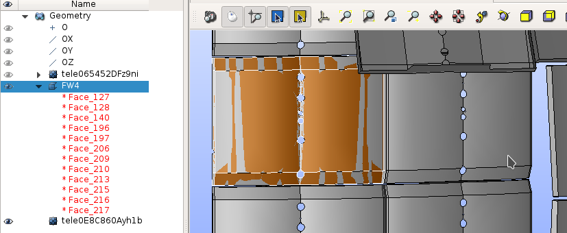
Note
When enabling FW4 and newly imported first wall for one segment
complete first wall we see shadow and target overlapping each other at
different areas. These slight differences are due to display
approximation only and does not affect actual shape processing and
meshing that is accurate at time of operation. The quality of display
approximation is controlled by
.
Changing from default 0.001 to 0.0001 will increase
display precision that can be sometimes confusing if not having this
in mind.
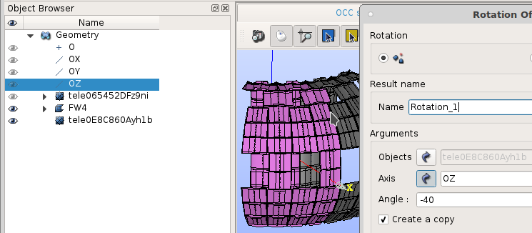
For preparing shadow around the target we could rotate the newly imported panels by selecting it and use menu . We select Axis by clicking OZ. Required angle of rotation is -40 degrees with Preview see that the panels combine quite nicely.
However, this means that we will have twice as much CAD geometry to mesh. Therefore, we restrict ourselves just to one blanket segment in CAD and replicate meshes as needed in Mesh module once we have them.
To complete this tutorial we just rename imported surface model to
PANELS and save the study somewhere for meshing.